Thrust Vector Control
C++ PID controller, simulated in MATLAB, and implemented to flight hardware
Overview
The thrust vector control (TVC) project set out to design, implement, and validate a two‐axis gimbal system for a small, high‐power rocket, with the overarching goal of achieving precise attitude stability throughout the ascent phase of flight. Key considerations included maintaining structural integrity under dynamic loads, minimizing added mass, ensuring mechanical compatibility with the existing airframe, and achieving responsive actuation within a ±8° deflection envelope.
To meet these requirements, a 2-axis gimbal mount was developed to integrate directly with the aft body‐tube coupler of the avionics bay, providing accurate alignment of the motor nozzle with the rocket’s center of mass while accommodating the required control torques. Mechanically, the gimbal mount was engineered to house two orthogonal axes of rotation—inner (pitch) and outer (yaw)—driven by standard hobby servos. Finite‐element considerations guided material selection and mounting geometry to resist bending moments at peak thrust, while precision machining defined the bearing seats and linkage interfaces to limit friction and backlash. A maximum gimbal angle of 8° was imposed both by mechanical design and control safety limits, with the neutral 1500 μs servo PWM corresponding to 0° and a mapping of ±10° per 1000 μs span implemented in software.
On the software side, the flight‐computer logic was developed in C++ as a robust state machine executing at 100 Hz. Incoming sensor data—including body‐frame accelerations, linear accelerations, and angular rates—are first smoothed via digital Butterworth filters (cutoff 5 Hz, sampling rate 100 Hz), implemented in ButterworthFilter.h and applied in the MEX interface of main_MATLAB.cpp. Subsequent processing transforms accelerations into the inertial frame via quaternion rotations, estimates velocity through Euler integration, and computes aerodynamic drag and thrust forces. Mass loss is modeled by decremental integration, which in turn updates the transverse moment of inertia to capture changing dynamics. Attitude control employs a quaternion‐based PID scheme—scaling proportional, integral, and derivative terms by a physical coefficient K = T*r/I—to generate a desired gimbal quaternion. Finally, computeServoPwms() converts this quaternion into inner and outer servo PWM commands, ensuring outputs remain within the mechanically safe ±8° range.
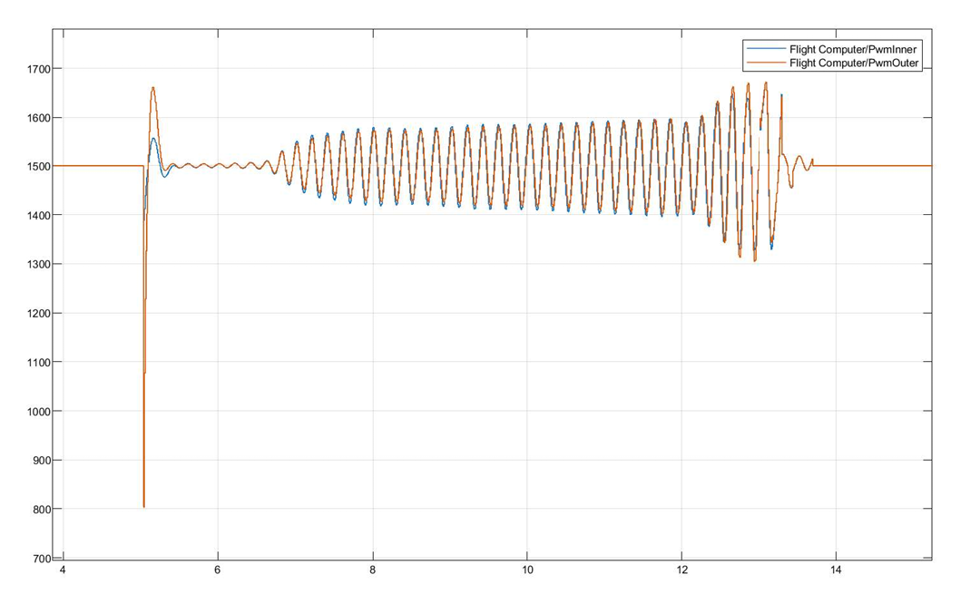
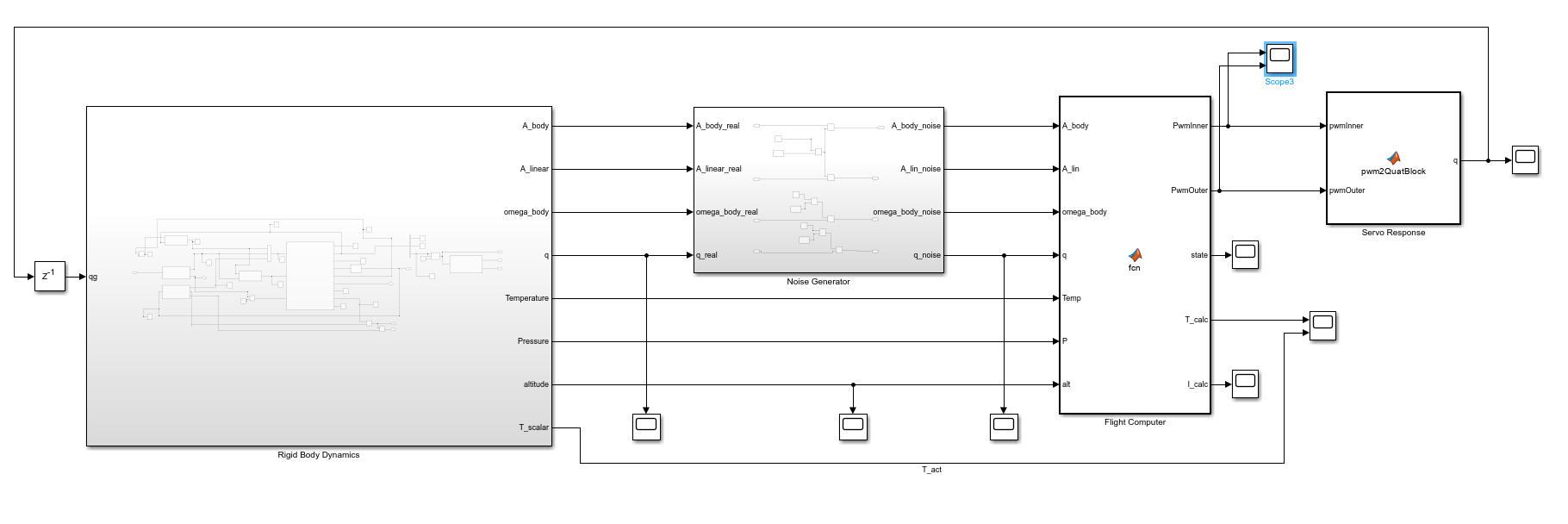
Prior to hardware testing, the entire control algorithm was validated in a MATLAB Simulink environment using the Aerospace Blockset’s 6-DoF quaternion block. The simulation architecture comprised three subsystems—rigid‐body dynamics, noise generation, and the flight computer—interconnected to emulate real‐world sensor noise, thrust profiles (from Aerotech I59WN-P motor data), and servo response. Quaternion kinematics, Newton’s translational and Euler rotational equations, and the gimbal mapping were all propagated through fixed‐step ODE solvers. Iterative tuning of filter parameters and PID gains in Simulink ensured stable attitude tracking and rapid disturbance rejection before proceeding to physical integration.